Here's a do-it-yourself method on how to build your very own bartop video arcade from an old PC.
![]()
![]()
![]()
![]()
![]()
![]()
![]()
![]()
![]() Now's the time to paint the arcade cabinet and control board. He used plain black spray paint.
Now's the time to paint the arcade cabinet and control board. He used plain black spray paint.
Step #8: Install Buttons and Joysticks
![]()
![]()
![]()
![]()
![]()
![]()
![]()
![]()
![]()
![]()
![]()
![]()
![]()
![]()
![]()
![]() Go find some arcade and console game ROMs (the internet is full of tutorials for how to do that) and start playing!
Go find some arcade and console game ROMs (the internet is full of tutorials for how to do that) and start playing!
If you want to see the full guide (write-up), go to this link later.![]()

Note: This DIY method on how to build your very own Bartop Video Arcade is not a guide made by Web Junkies Blog. It is created by David Beauchamp and was posted on this blog to serve as a guide for one of our editor as he is making one in the process :). And of course, for those techies and DIY-er's out there who are a fan of our blog. So basically, if someone deserves credits, it should be David Beauchamp.
How to Build Your Own Bartop Video Arcade from an Old Computer
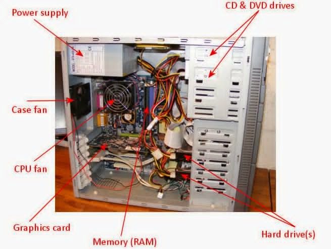
Step #1: Computer and Parts
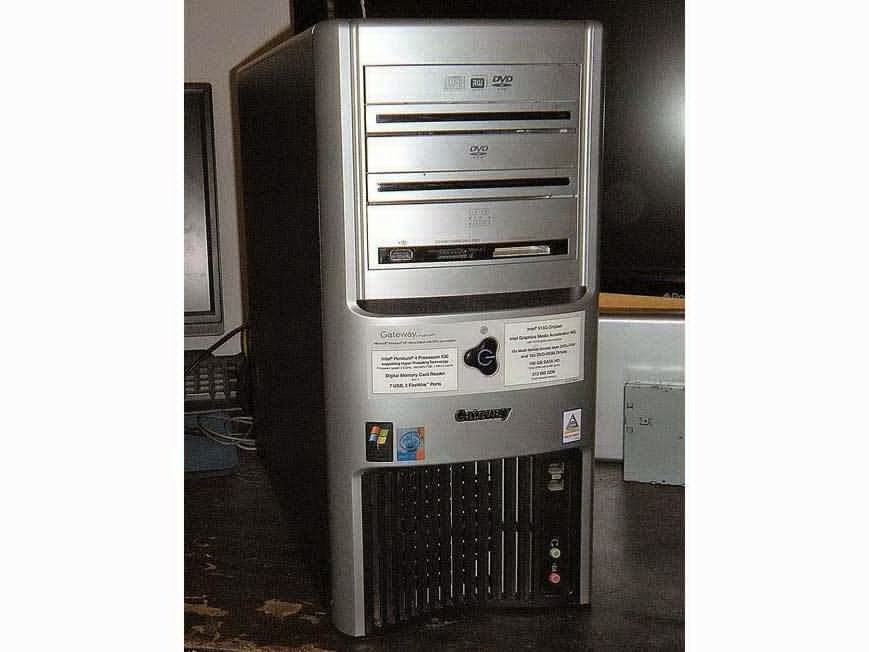
- David's old Gateway desktop computer was outdated by today's standards but perfect for this project. This PC supplied the majority of the parts.
- The computer specs are: Intel Pentium 4 3.4GHz processor, 400 watt power supply (that's more than enough), 200 gigabyte IDE hard disc drive, 2GB of RAM, and Nvidia video card with another 1GB of memory.
Step #2: Computer Monitor/arcade screen
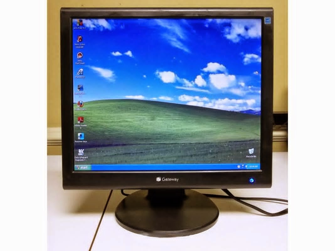
- He wanted to find a computer monitor with a standard VGA input to use as the arcade screen. With a quick search on Craigslist I found a lightly used 4:3 (non-widescreen) monitor for only $25.
- NOTE: Most new monitors are widescreen and would not fit in this build. But more important is the fact that these classic arcade and console games were made for the traditional 4:3 television and computer monitor display.
Step #3: Blueprints
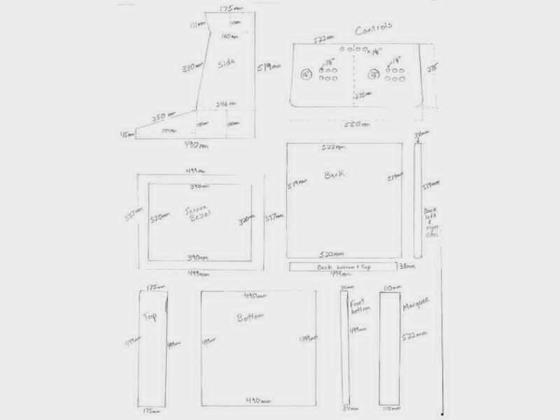
Step #4: Cutting the Pieces
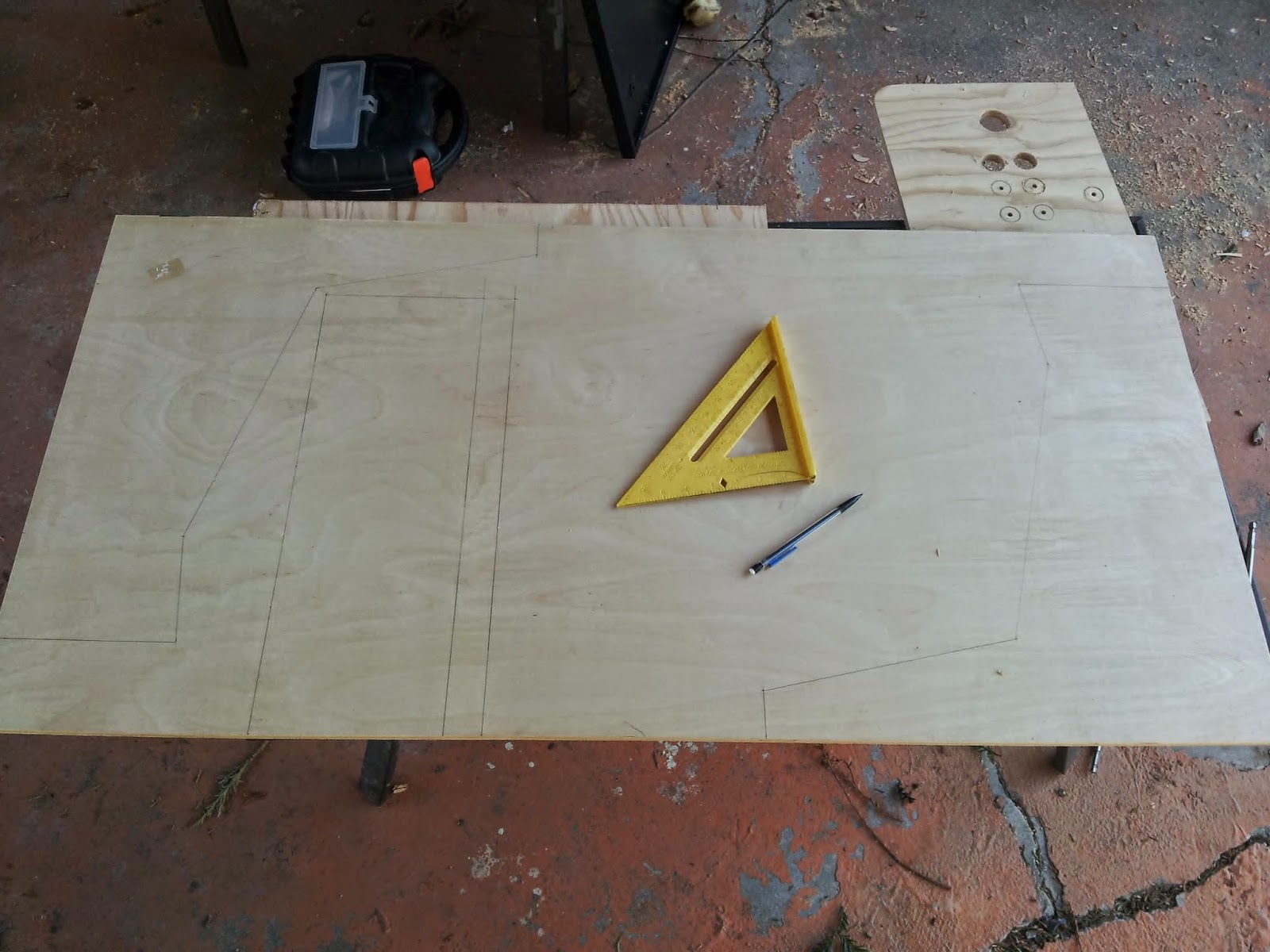
- Cut out the plywood pieces following the blueprints.
- He picked up the wood and hardware at Home Depot. The plywood is ½" birch that comes in 2'×4' sheets. He ended up buying 3 of these sheets. At $12 a sheet it was not too expensive.
Step #5: Build the Frame
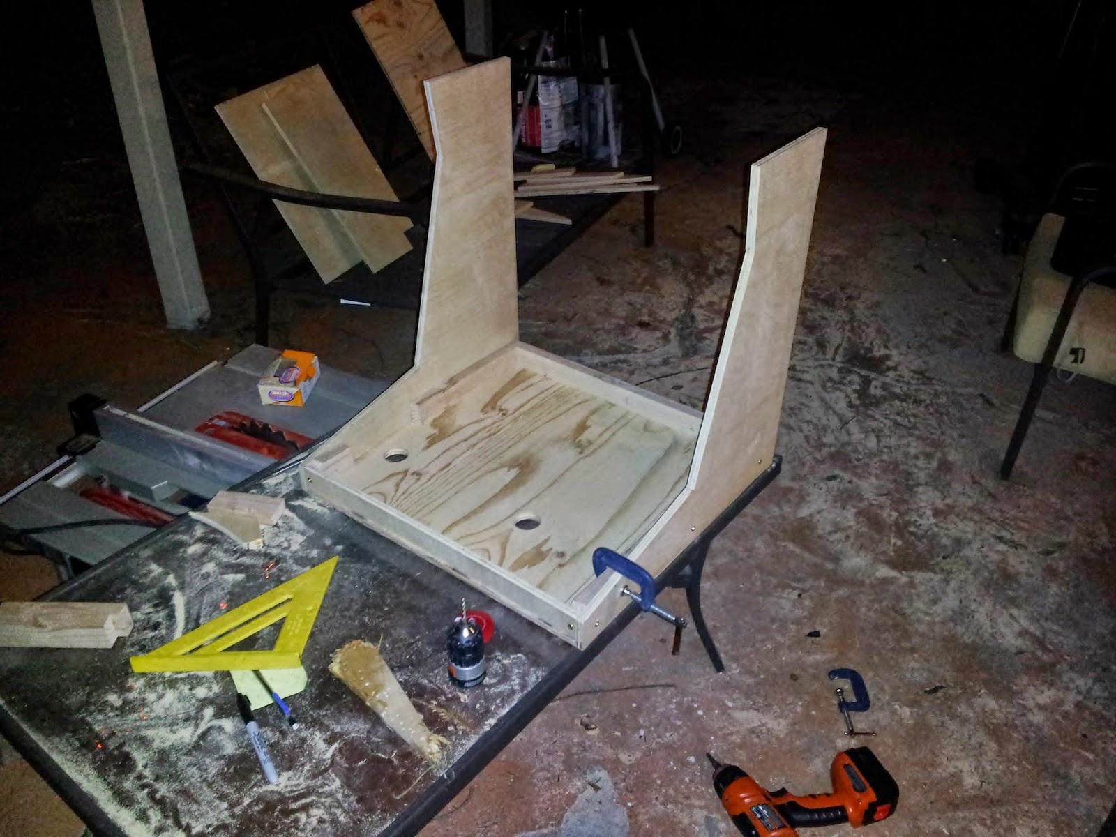
- Use 1×2 pine reinforcements in all the corners for stability. These boards came in 8' pieces and only cost about $2 each.
- I have seen other arcade makers use aluminum angle for this same purpose.
- The 2 holes in the bottom were cut out because the joysticks were longer than I expected and needed some more leg room.
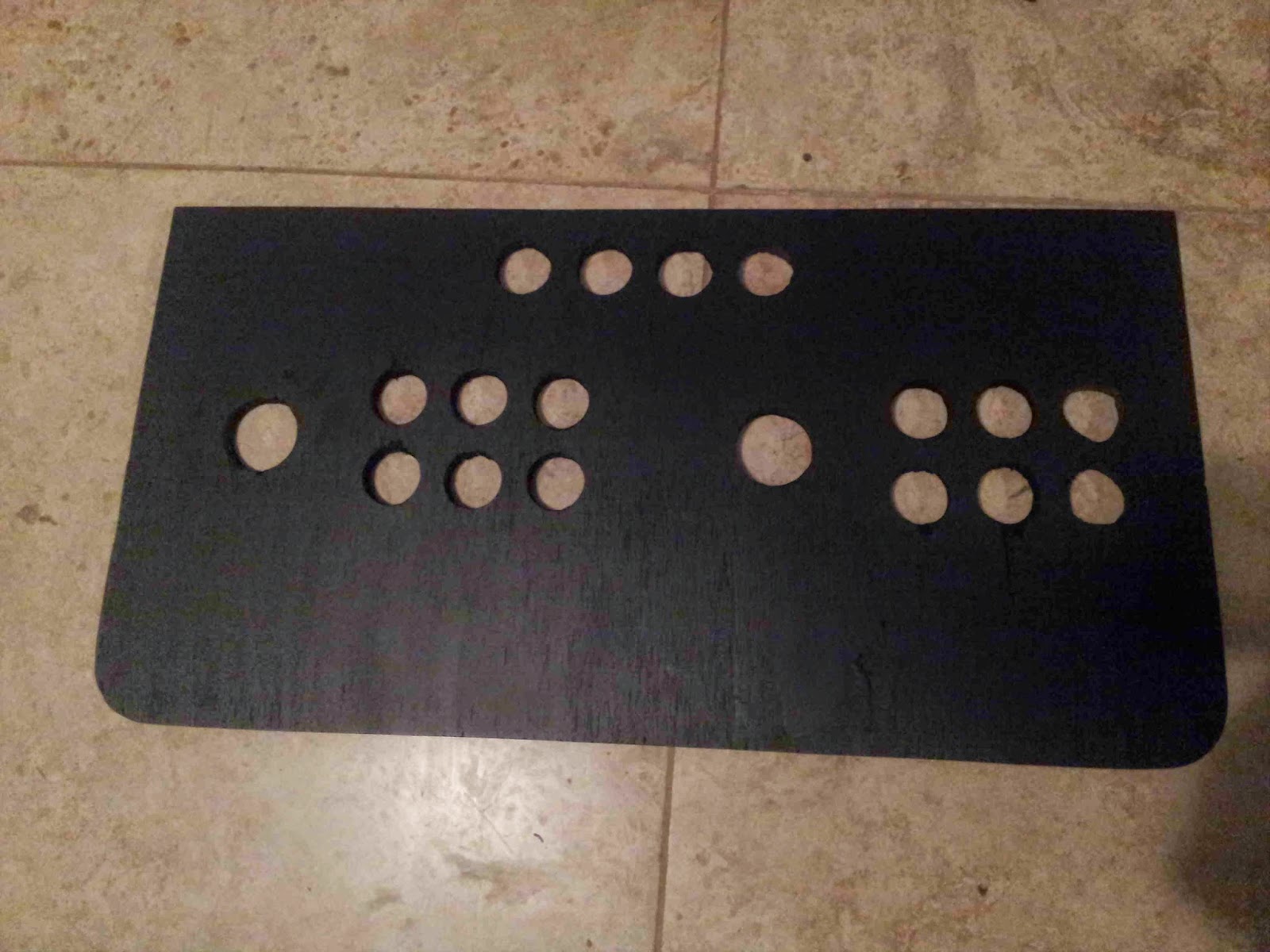
Step #6: Layout the control panel

- He measured by placing the joysticks and buttons on the panel to figure out the placement of everything. The joystick holes were drilled out with a 1½" bit, and the button holes with a 1⅛" bit.
- He tried to put as much space between Player 1 and Player 2 as possible while still staying within the bounds of the side walls. (Some wall modification was needed with a Dremel tool due to miscalculation.)
Step #7: Paint
Step #8: Install Buttons and Joysticks
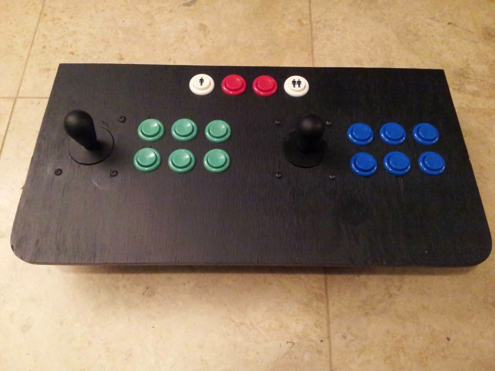
- Insert the buttons, and screw on their nuts.
- The joysticks didn't come with nuts and bolts but these were easy to find at Home Depot. I found some nice low-profile black screws with Allen wrench tops that look good.
- Now connect all the click switches to the bottom of every button and to all 4 directions of each joystick.
Step #9: About the USB controls panel

- The joysticks and buttons he bought in one nice convenient package on eBay. For $50 the kit had 2 joysticks, 16 buttons (any color), all the wiring, and the Xin Mo 2-player USB adapter.
- With this kit there's no soldering or wire cutting needed. You'll just connect everything up and then plug the Xin Mo adapter to the computer via USB ... simple.
- Other USB controls adapters you can try: I-PAC, J-PAC, and THT.
Step #10: Connect Buttons and joysticks to USB adapter

- He marked the button numbers next to the buttons so he knew which spot to plug the wires into the USB adapter. You can configure the buttons in software to do whatever you want them to do, but wiring them up correctly by the directions in the beginning makes the default controls work out of the box.
- There's a ground wire and a "live" wire to plug into each switch. The ground wires all connect in one big daisy chain. And the "live" wires connect separately into their own spot on the Xin Mo adapter.
- Mount the USB adapter to the bottom of the control panel with the included screws and standoffs.
Step 11: Mount the control panel

- He attached the control panel to the cabinet with simple kitchen cabinet hinges.
- This lets me keep the computer's wireless keyboard/mouse and AC power cable inside it for storage.
- Those 2 items are the only external parts of this arcade.
Step 12: Mount the computer parts
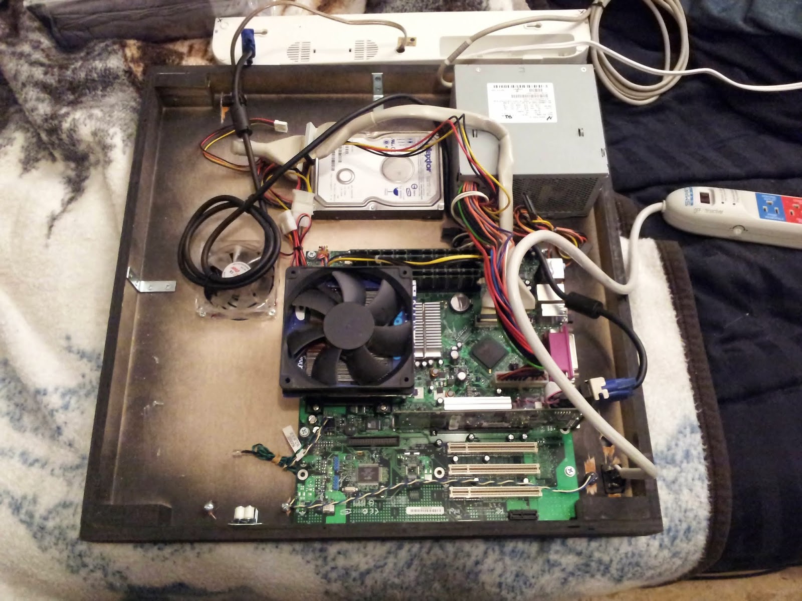
- He mounted the motherboard onto the back panel of the arcade cabinet with some grommets and a few wood screws.
- The hard drive and power supply are glued onto the back panel with 5-minute epoxy.
- He couldn't find a heat sink and fan for the CPU that would fit inside the cabinet. So he built my own with a short heat sink, screwed into the back panel, and glued on an extra fan he had. He even had a little help from a Bed Bath & Beyond ad flyer to help direct airflow for the fan.
Step #13: Wire the On Switch
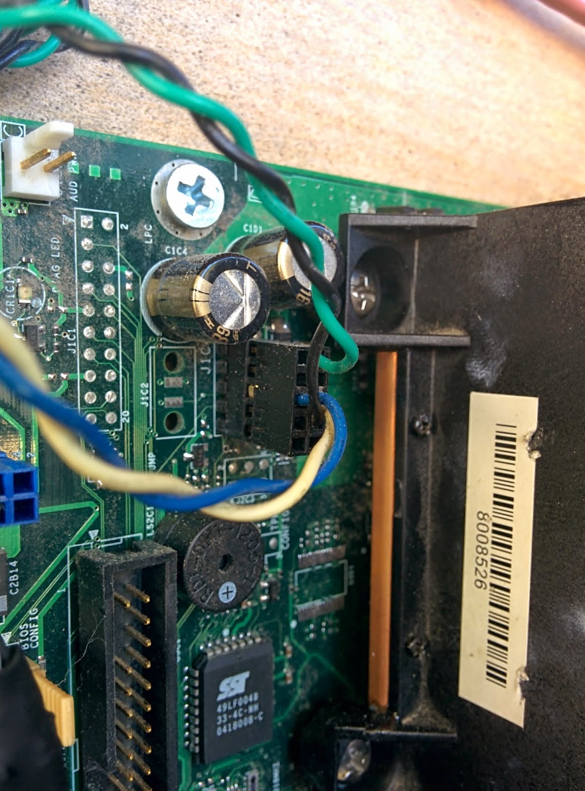
- He is using a momentary-on pushbutton switch, SPST (single pole, single throw) to turn on the computer. After taking a look at the motherboard's manual he found that the blue and white wires that used to connect to the desktop PC's power switch can be wired to this momentary-on switch to turn the computer on.
- Use a 25W soldering iron here.
Step #14: Route the AC Power
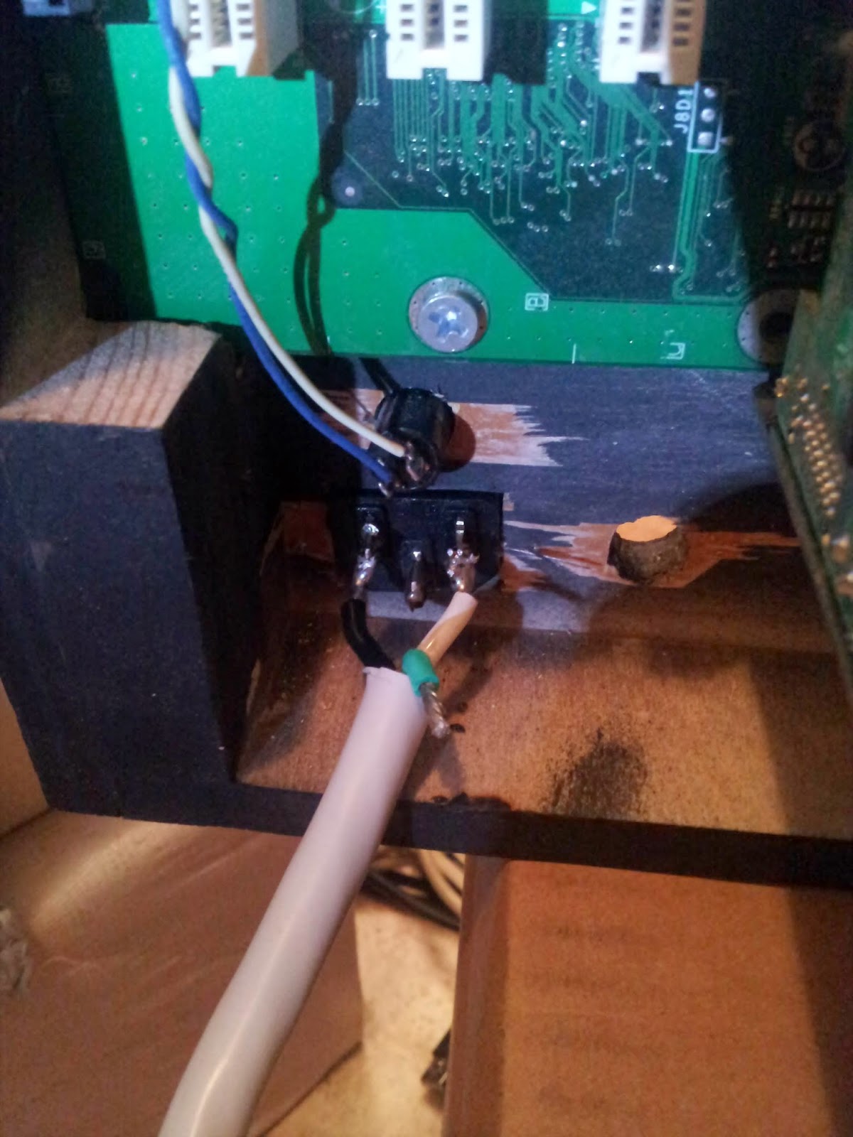
- He cut the end off the "smart" power outlet extension and wired it to the PC's power cable connector he mounted to the back panel.
- The smart power outlet extension will turn everything on at once when the computer is turned on, and then turns everything off at once when the computer is turned off. This is nice for controlling the monitor, audio amp, and marquee light, but it's not necessary. A normal power strip would work fine.
Step #15: Install the Speakers
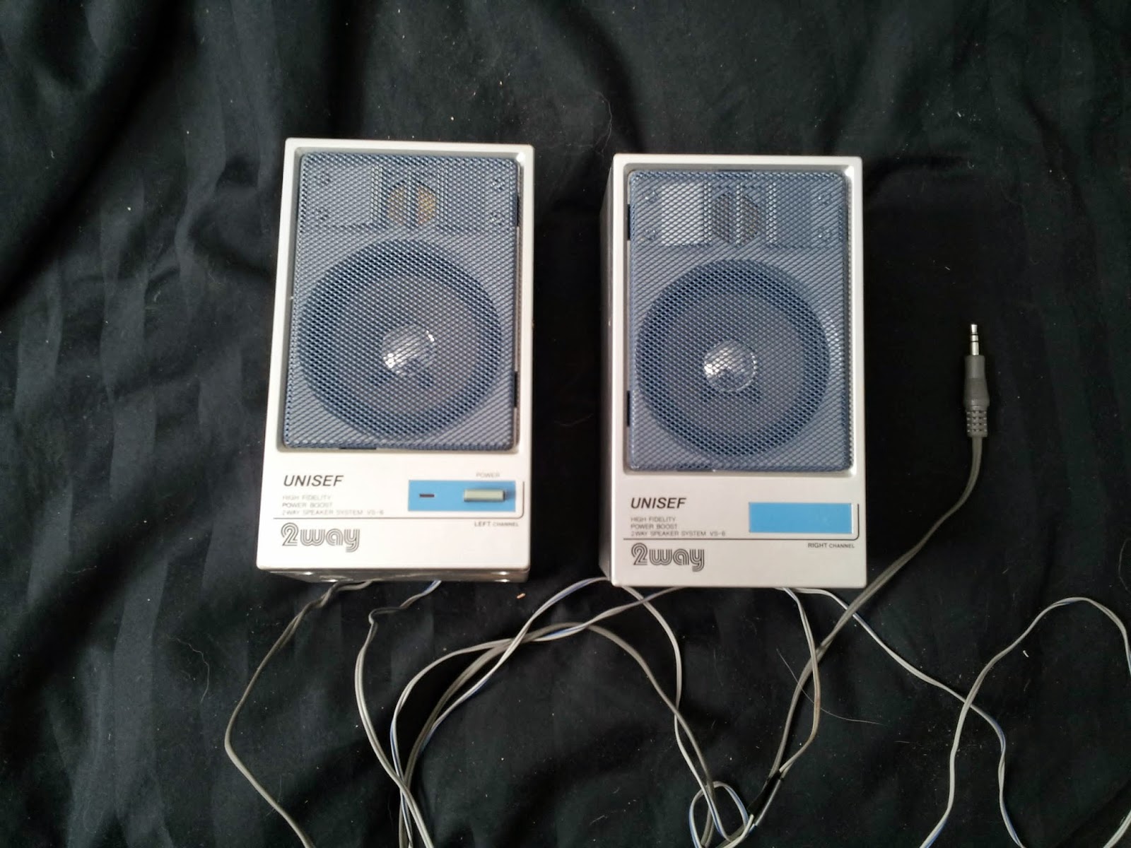
- These 2.5" speakers were taken out of a cheap computer desktop speaker set. Measure yours and cut holes to mount them just behind the marquee.
- The speakers had a built-in low wattage amp that's powered by 6V. He mounted the small speaker amplifier to the inside wall of the cabinet, then soldered the speaker wires to the speakers and plugged the input jack into the audio output of the computer motherboard.
- The amp is powered by a multi-voltage AC adapter set to 6V. Your setup may vary.
Step #16: Install intake and outtake fans
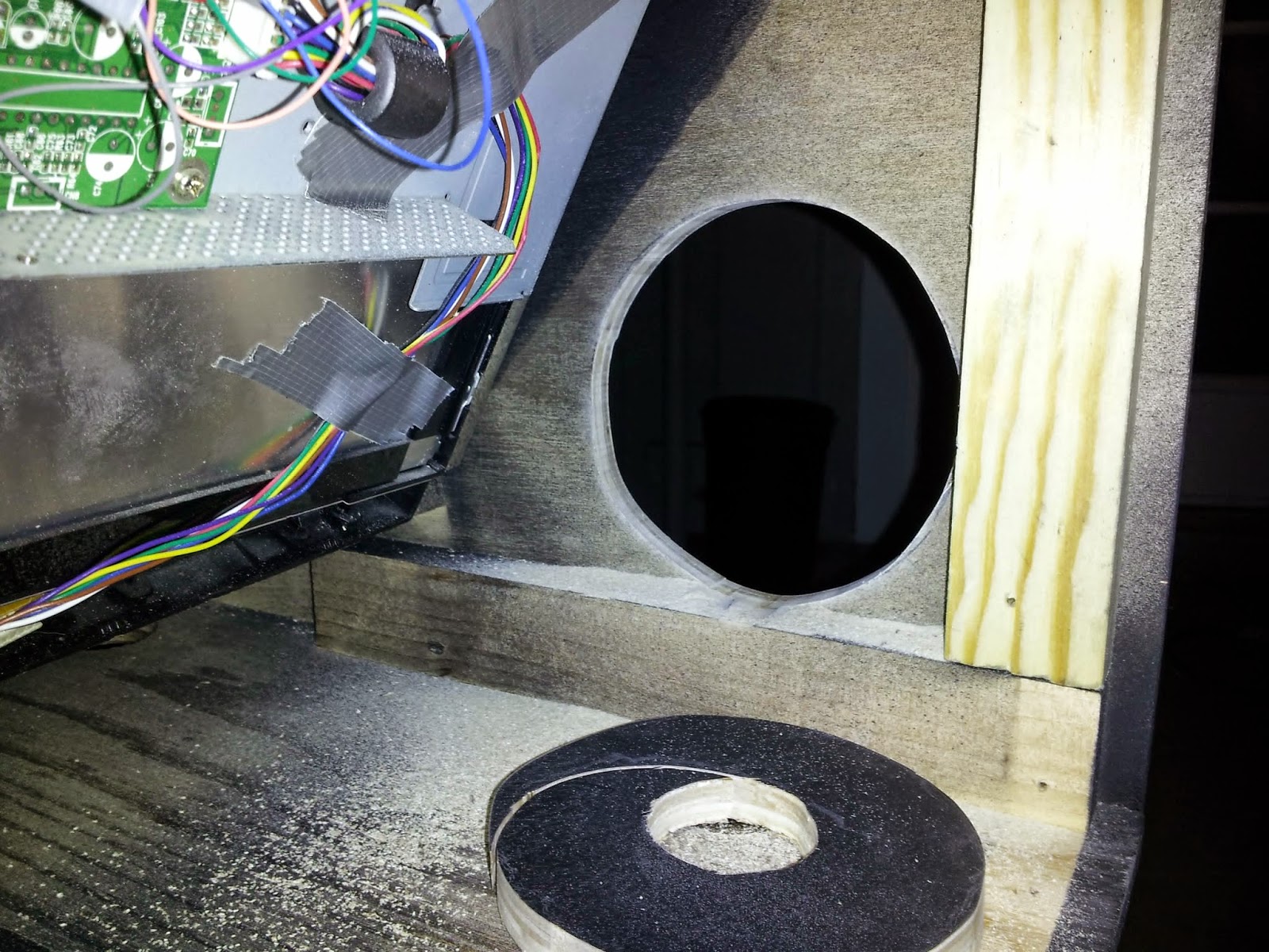
- He used the fans from the computer for these. Drill a hole to insert the jigsaw blade so you can cut a circular hole for each fan.
- A 4½" fan was used for the air intake on the bottom right side of the cabinet.
- Then another 3" fan was mounted on the back panel to pull the air out.
Step #17: Mount the back panel

- Mount the back panel to the cabinet with large hinges on one side.
- Install a kitchen cabinet latch on the other side.
Step #18: Finish the back and bottom panels
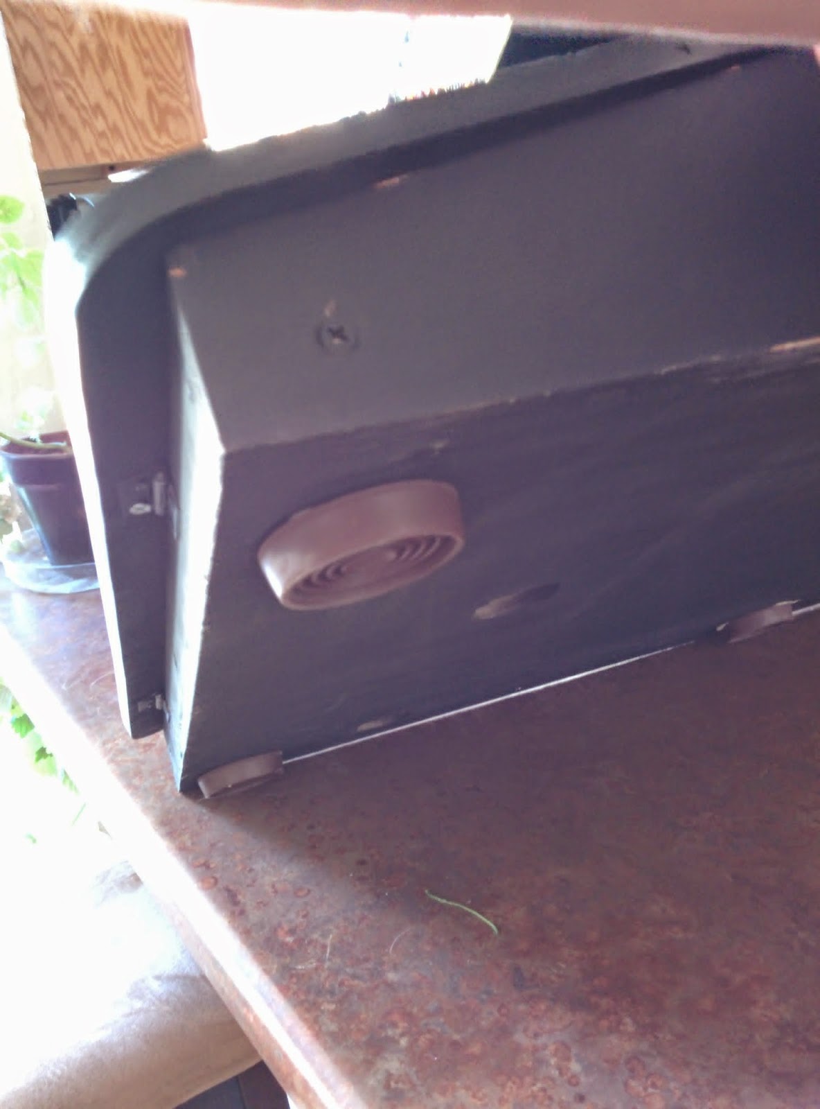
- On the bottom panel, glue large nonslip rubber feet in all 4 corners.
- He added a simple kitchen cabinet handle spray-painted black for opening the back panel.
- He also installed a dual USB adapter on the back panel for quick and easy transferring of files.
Step #19: Make the marquee

- He used 0.1" acrylic (plexiglass) for the arcade marquee. With a few slices of the acrylic cutting knife, the piece I needed was ready to break off.
- He printed the sticker on 2 sheets of 11"x17" normal adhesive paper. (The marquee was almost 21" long so printing it on a single sheet was not possible on the basic office printer he printed it with.)
Step #20: Add a marquee backlight

- He found a 16" fluorescent light for $8 that he used to light up the marquee. He removed its on-off switch and wired in a cable to connect to a new, heavy duty external on-off switch, which he mounted on the back panel up high near the marquee.
- This fluorescent light fixture fits perfectly inside the cabinet behind the marquee. It's such a tight fit that no screws or glue is needed to keep it in place. Yours may vary.
Step #21: Mount the screeen
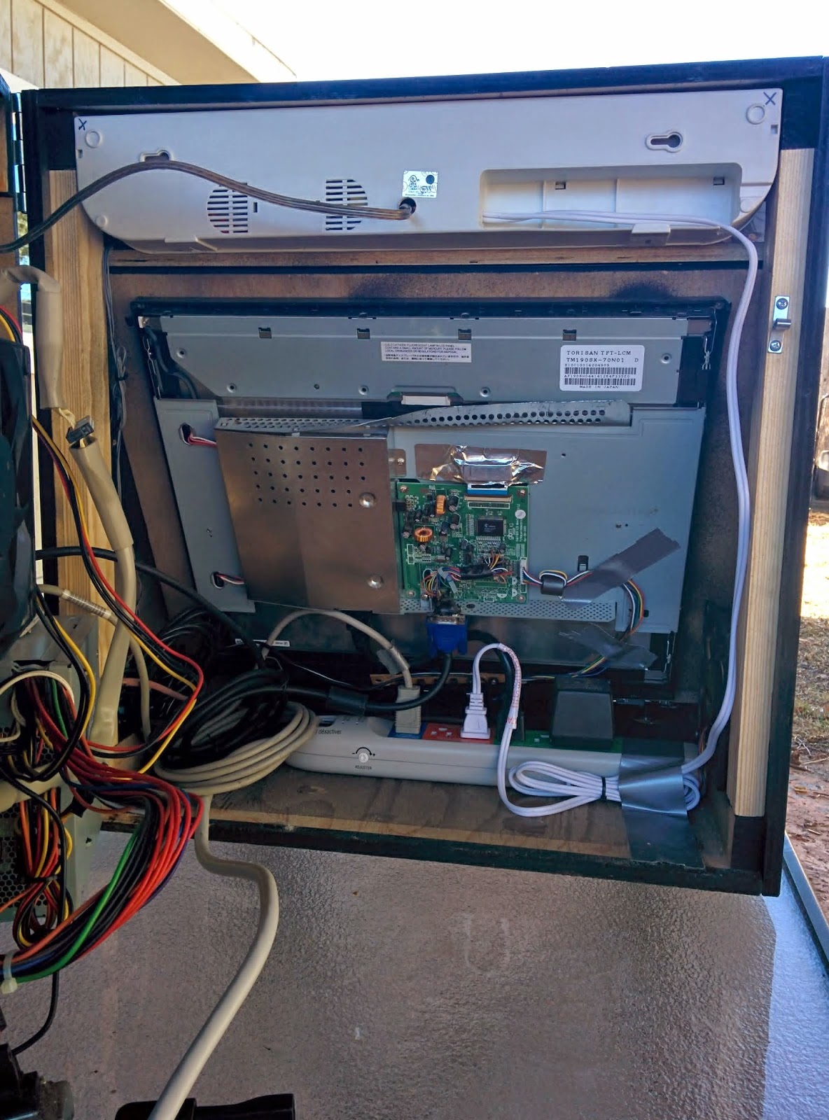
- Mount the monitor inside the arcade cabinet's front panel.
- Mine was mounted by taking the monitor's back panel off and drilling in 4 screws into the corners. The back of the monitor popped off easily with some help from a flat-head screwdriver.
- Your Bartop Arcade is built! Now let's install the game systems.
Step #22: Operating System and emulator software
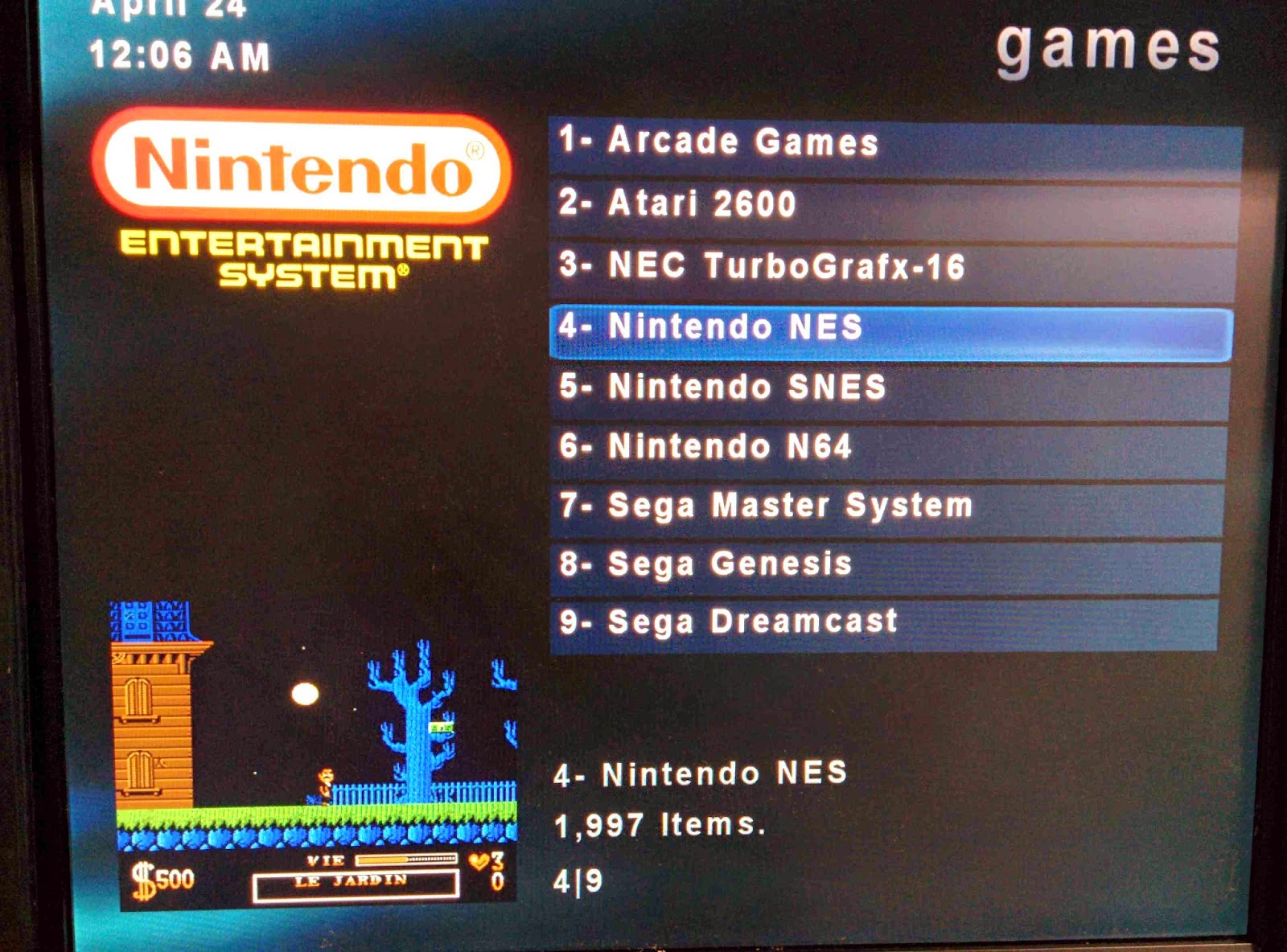
- He installed Windows XP because this operating system does not require much from the hardware. With only 2 gigs of RAM, this old computer would run much slower with Windows 7 or 8. Linux is an option but the emulation programs are much easier to work with in Windows and these programs are not all written for Linux.
- Now install your emulator software. He recommend installing MESS for running Atari 2600 and 5200 games, Jnes for Nintendo (NES) games, ZSNES for Super Nintendo (Super NES) games, Project 64 for Nintendo 64 games, Fusion for Sega Sega-Genesis 32x and Sega CD games, and of course MAME for running any game that was on an arcade machine. If your system is fast enough then try Dolphin to run Nintendo Gamecube or Wii games.
- A Logitech K400R mini wireless keyboard is used when dealing with the software or operating system. Once inside the emulator software and playing games, the keyboard is tucked away and not needed.
Step #23: Time to play some games

If you want to see the full guide (write-up), go to this link later.